Week Review 3/14/2024
Float PCB
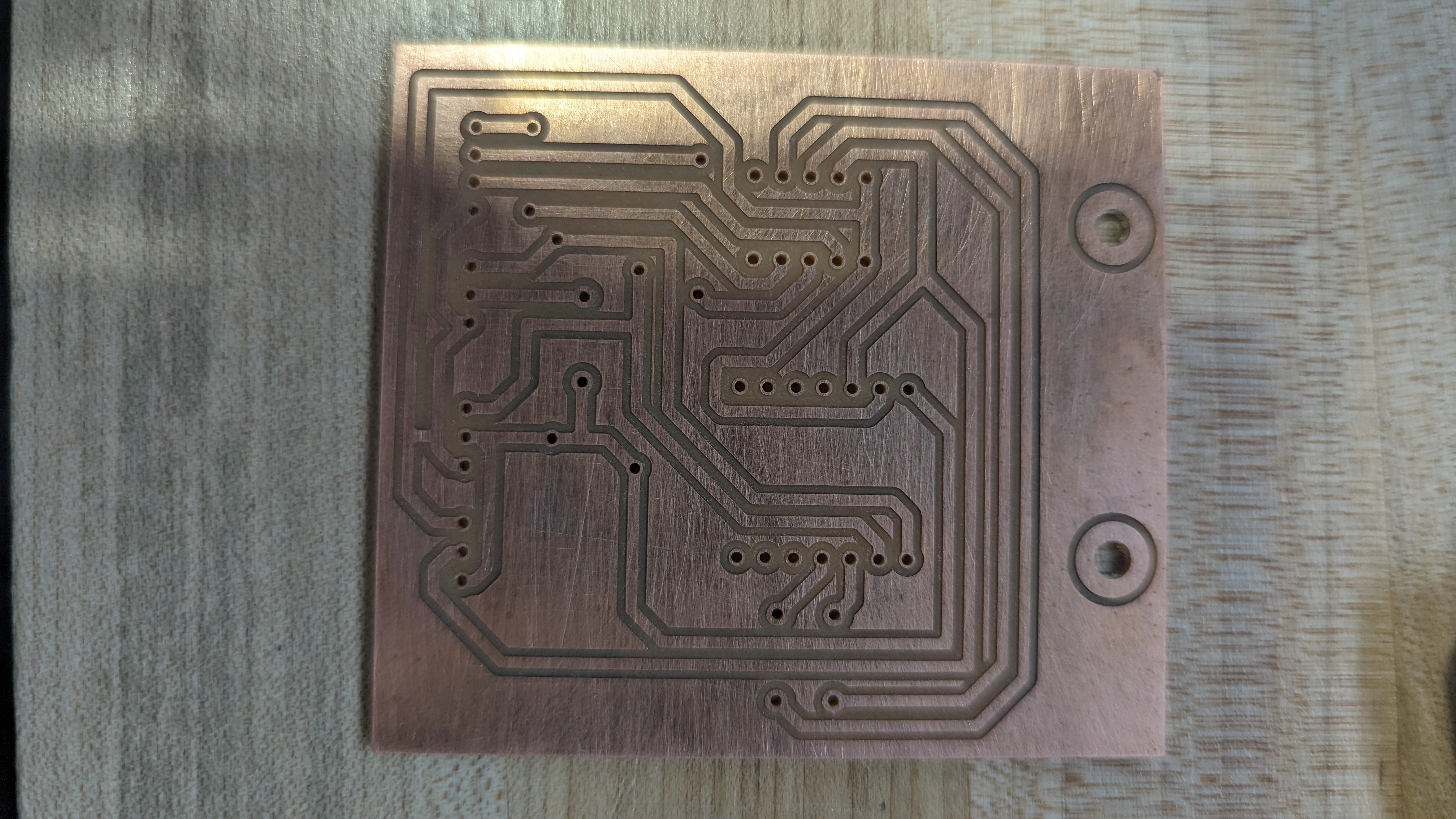
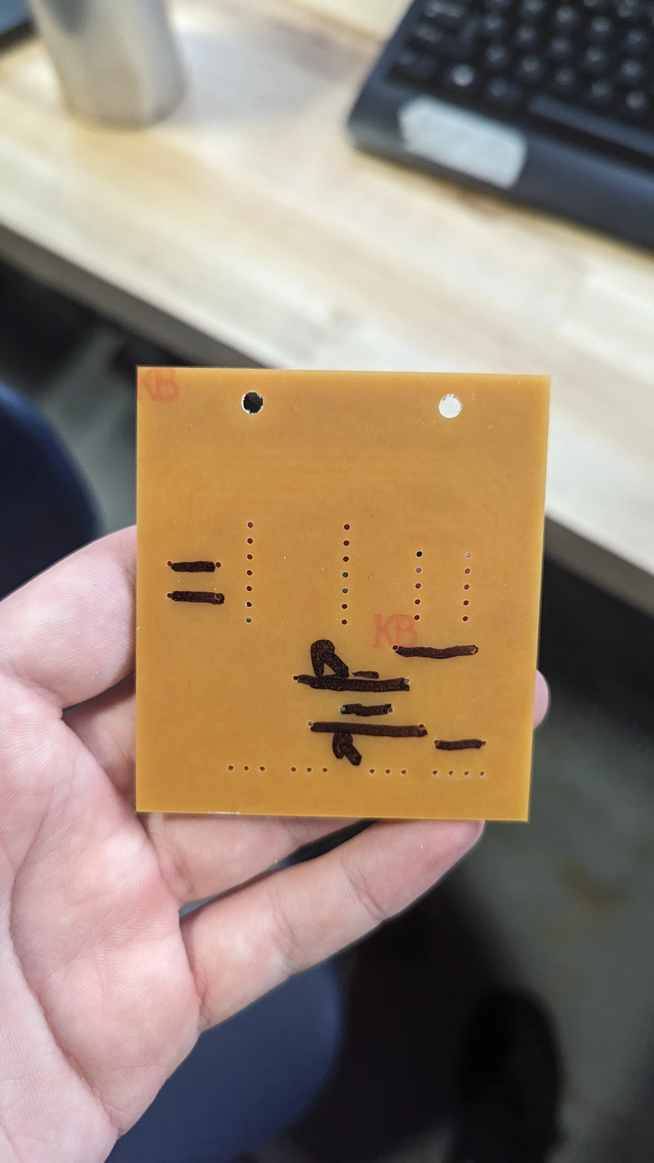
I finished the schematics for the float PCB last week, but it took me a long time to route it. I had to use jumper cables to jump between traces because I was not able to fit everything on one layer.
I made sure that the hall effect sensors are actually getting 5 volts and getting pulled up to 5 volts. I am hoping that it will be more reliable because of that change. To get 5v I had to break in another tap from the battery pack.
KiCad by default does not support using jumper wires so I had to find a workaround. I made a footprint and a zero resistance resistance that were the correct length for the jump. I did not have enough time to soldier the board, but I did have enough time to cut it.
The way I had to do it for the home mills we have is a little bit ugly, and not as reliable as a properly fabricated PCB so I will make one in a board house if the PCB works.
Float Code
In order to make the float reliable I needed to make the code accept two hall effect sensors. I made two interrupts, one for each sensor. When the sensor falls it sets a flag called hall_effect_triggered_1 or hall_effect_triggered_2 to true.
When I tested the code with the breadboard it seemed to be very reliable. Although there have been a lot of issues with the sensors I am hopeful that we are getting them out of the way now and will not struggle with them later.